E-Bike
Tekerni. No de most a pedált, vagy a gázkart?
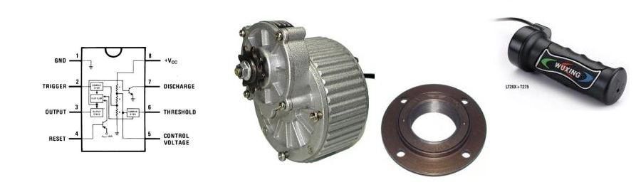
This controller is a simple circuit with a 555 timer and some extra parts.
Here is the 555 IC:

The basic circuit:

The 555 IC is a very flexible one, so it’s good for this job too. Lots of extra thing can be solved with it. E.g. for baning, connect the „Reset” leg to the ground and the output will be zero. If we connect a voltage from 0V to Vcc to the „Control” leg, we will have a PWM signal on the output and the fill out factor is proportional with the input voltage. The frequency of the PWM signal is determined by two resistors and a capacitor. I’ve chosen the combination of 47kΩ and 1nF, it determines the frequency somewhere between 15-20kHz.
I found a very good java application, where you can study the PWM among some other basic circuits. The PWM circuit you can find here is the base of my basic circuit.
Here it is: java
My basic circuit is differs from the offered one by this java application. The difference is that the „Discharge” leg is connected to the output instead of Vcc. The main reason, that the theoretics is differs from practice and I felt a better control with this feedback connection. Maybe somebody with a biger knowledge can tell a bit more about it, but it is just a personal experience. The output of the 555 IC is connected to the Gate of an IRF640N FET. During the test I use 2pcs of 18650 LiIon cells for powering the system. It works quite good, but I’ve met again with an effect which prooved again that theoretics is differs from practice. It’s nothing else, but the real variability of the fill out factor. Unfortunately it cannot be adjusted between 0% and 100%, but approx. 1,5% to 98,5%. It can be seen on the video as well, because at the adjusted zero voltage you can hear the „whistling” output, so we have a measurable signal which you can see on the video as well. I will compensate it later, but let’s see the test of the basic circuit first.
Here it is: test